Design and Validation Testing of Jumper Breakaway Joints
Operators of offshore oil & gas wells and pipelines are required to ensure the safety and reliability of permanently installed equipment, even in the aftermath of unplanned extreme events. One effective option for these scenarios is installation of a properly designed and tested weak point in a replaceable part of the system.
For decades, Stress Engineering Services has been analyzing, designing, and performing validation testing of subsea jumpers and their breakaway joints for clients around the world. A critical aspect of the design requirements for these types of subsea jumpers is to incorporate a breakaway joint in the jumper configuration that would meet the normal design operating conditions but also ensure that the jumper would break (fail) at a designated location on the jumper when it experiences a set maximum load.
This breakaway feature of the jumper design ensures the protection of the connectors on the subsea manifolds and the PLET to which the jumpers are connected. This feature is meant to protect expensive and long-lead structural items from accidental failure due to an anchor snag of the pipeline connected to the PLET. Incorporation of a breakaway joint in the subsea jumper configuration provides a controlled failure mode of the jumper against a pipeline anchor drag. The typical design and analysis investigates a series of “U” and “M” shaped jumper configurations and notched failure-point geometries to achieve the desired objective.
1. A lower-bound limit that specifies a minimum strength that the breakaway joint has to achieve to meet the normal and extreme operating conditions.
2. An upper-bound limit that ensures that the joint would fail in a controlled manner at a very specific bending moment.
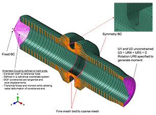
Figure 1: Finite element model of a Breakaway Joint
For one of our clients, we performed a nonlinear elastic-plastic finite element analysis to establish the capacity of a jumper and breakaway joint. Figure 1 shows a half-symmetry finite element model of the breakaway. The material properties for the analysis were based on tensile tests on specimens taken from prolongations on the actual breakaway joint forgings. The results of the analysis verified that the breakaway joint notch is the weak point in the final jumper configuration, with a moment capacity well below the rated capacity of the manifold connectors.
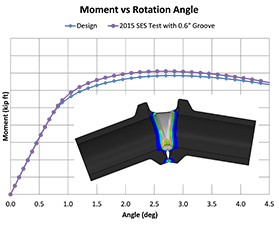
Figure 2: FEA results – moment capacity of Breakaway Joint
Figure 2 shows the predicted and measured bending moment capacity response of the breakaway joint as it is taken to failure. The fatigue analysis indicated that the design life of the breakaway joint is greater than that of the jumper assembly welds.
We then conducted validation tests to confirm the design of the jumper and breakaway joint. A pure bending test was performed on the breakaway joint while a full-scale test was performed on a portion of the jumper.
The pure bending test of the breakaway joint was performed using our Reel Frame (Figure 3). The purpose of this test was to verify the bending moment capacity of the breakaway joint before performing a full-scale failure test of the jumper. Figure 3 also shows the breakaway joint sample after failure in bending. Figure 4 provides a comparison of the measured versus predicted loads. It can be seen that excellent agreement was achieved between the measured and predicted moment capacities of this breakaway joint.
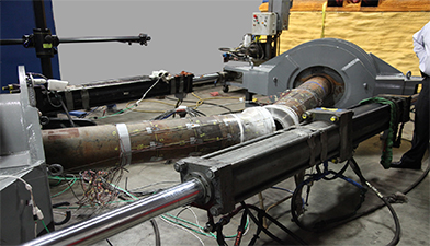
Figure 3: Breakaway Joint following failure in bending
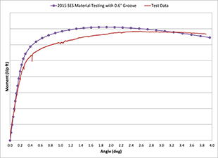
Figure 4: Predicted versus measured moment capacity of Breakaway Joint
We also designed and fabricated a test fixture for the specific purpose of performing full-scale pull tests on quarter jumpers. This pull test is intended to simulate a pipeline anchor snag event. The frame was designed long enough to accommodate a piston stroke sufficient to ensure that the quarter jumper would fail in a single, continuous pull. The pull frame was designed to accommodate a maximum piston stroke of 30 feet, a maximum pull load of 500 kips, with a reacting bending moment of 5,000 ft-kips. Figure 5 shows a quarter jumper sample installed in the pull test frame.
Strain gauges, a data-acquisition system, and a video system were used to measure and record the strains and displacements along the quarter-jumper test sample. Figures 6 and 7 provide a comparison of the measured versus predicted bending moment response of the quarter jumper, and the measured versus predicted piston load required to fail the breakaway joint. As seen, there is excellent agreement between the measured and predicted capacity of the breakaway joint.
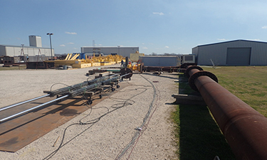
Figure 5: Full-scale Quarter Jumper in pull frame
Results, Observations, and Conclusions
We found that the jumper design was successful in satisfying the dual objectives of conformance to code requirements and failure at a predictable location and load. Design verification analyses using nonlinear elastic-plastic material properties taken from prolongations on the breakaway joint forgings accurately predicted the maximum load capacity of the design. Full-scale validation testing confirmed the predicted failure location and the maximum load capacity of the joint within 4% of the predicted value.
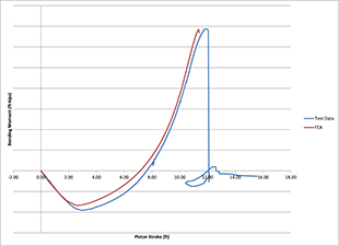
Figure 6: Measured versus predicted bending moments for Breakaway Joint
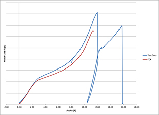
Figure 7: Measured versus predicted piston loads for Breakaway Joint
** This article appears in the 2017 issue of Stress Talk **

Rafik Boubenider, PhD, PE – Principal, Houston Office
Rafik has been a valued part of the Stress Engineering Services team for more than 25 years. He specializes in the design and analysis of drilling structures; drilling, production and export risers (TTR’s); Steel Catenary risers (SCR’s), failure analysis; dynamic and fatigue analysis; and foundations. He is also an expert in the use of non-linear finite element analysis for the study of structural and mechanical components.


Leave a Comment
You must Register or Login to post a comment.