Conductor Casing Pile Driving Assessment
Testing and Monitoring a Large-Diameter Conductor Casing Connection During Hammering Installation and Assessing Its Performance
Stress Engineering Services, Inc. recently conducted field testing to assess the performance of a large-diameter conductor casing connector during a simulated pile-driving installation. High-speed strain gage and accelerometer data, advanced deformation measurements, and combined load sealability testing were used to evaluate overall performance of the connector after pile driving.
Background
During drilling operations, the first piece of pipe to be installed in the ground is typically the conductor casing. This section of the well can be installed up to a depth of roughly 150 feet. Conductor casing can be run into pre-drilled holes, water-jetted, or inserted into the ground through a method of hammering or driving. Hammering can be particularly hazardous for threaded connectors because the connection’s sealability performance can be damaged from the high impact energy imparted by the hammer blows.
API’s Recommended Practice 5C5 on “Procedures for Testing Casing and Tubing Connections” requires the connection’s integrity not be compromised by shock loadings and recommends that the connector’s integrity be confirmed via full-scale testing. While some general testing guidance is provided, it is not specific enough to design a full testing program. Stress Engineering worked closely with one client to develop a stringent testing program that would mimic real-world field installation conditions while gathering the most information possible in an economical and time-efficient way.
The testing program utilized an existing “refused” pile that extended over 400 feet deep into the ground. A pile is a length of pipe driven into the ground and is considered to be “refused” or “at refusal” when 250 impacting blows with the hammer move the pile less than 12” into the ground. Using a refused pile during testing was important because it most accurately represented the most severe conditions a connector could experience during installation. The hammer installed on the test sample is shown in Figure 1.
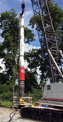
Figure 1: Hydraulic hammer on top of casing test sample
Pile-driving hammers typically operate by lifting a heavy weight (called a ram) and then using gravity or compressed fluid to drive a section of pipe into the ground. When a pipe is driven with hammer blows, the impact from the hammer creates a compressive shock wave that travels down the length of the pile at roughly the speed of sound in steel. After the stress wave reaches the bottom, an inertial effect causes the stress wave to be reflected and travel back up the pipe as a tension wave. These high-speed alternating tension and compression waves can impart severe damage to a threaded connection and are why it was important to capture this phenomenon via testing.
As the pile moves, much of the energy from the impacting shock wave is absorbed into the ground. Once at refusal, there is no major movement of the pipe and, therefore, the resulting energy transferred through the connections higher than at any other time during the hammer driving installation process. Due to these complex high-energy loading conditions and the need for connections to seal against well-bore fluids without leaking, full-scale testing is important to demonstrate the performance and reliability of the connection following hammering.
During the installation of a conductor pile, the first connection placed into the ground will experience the least amount of impact energy but the highest number of hammer blows. By contrast, the last connection in the pile will experience the lowest number of blows but at the highest impact energy levels. Stress Engineering designed a test plan that systematically increased the amount of energy and number of blows such that the connection could be analyzed after each increasing step and both loading scenarios considered. At the end of the testing program, the sample was to be exposed to a greater-than-typical number of hammer blows at a higher-than-typical energy level, after which it would be evaluated for performance in terms of galling tendency and sealability.
Test Set-up and Equipment
A threaded conductor connector welded to a section of 30” OD and 1” WT pipe was used as the test sample. To simulate real-world hammer blows, an industrial IHC Hydrohammer® S-150 hydraulic hammer was used for the testing. This hammer can impart maximum energies of up to 150 kJ (111 ft·kip) into the pile. The primary application for this model of hammer is driving steel piles and casing in onshore, offshore, and underwater environments. A typical field installation for 30” OD 1” WT pipe would employ an S-90 (90 kJ) size hammer. However, the larger S-150 model (150 kJ capacity) was chosen for this program because its energy could be reduced to simulate the S-90 operation as well as used to apply extreme energy levels to the test samples that would be greater than typical.
The hammer system ram velocity, ram stroke, number of blows per minute, and blow energy were all recorded during testing.
To quantify the energy imparted onto the test sample during hammering, biaxial and triaxial strain gages were installed on the connection and pipe body. Over 30 strain-gage rosettes were installed per sample to monitor the stress and deformation in the connector and pipe body. The recorded strain data were used to determine the maximum von Mises equivalent (VME) stress imparted to the samples during hammering to monitor for excessive stresses.
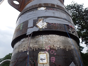
Figure 2: Test sample connection showing environmentally protected strain gages
A photograph of typical strain gages attached to the test sample is shown in Figure 2. Accelerometers were also installed on the connection to measure the g-forces transferred through the connection during hammer blows. The testing instruments and transducers were protected from the harsh outdoor environmental conditions.
To better capture peak strain and acceleration measurements during these impact events, Stress Engineering’s advanced data-acquisition system was used to scan all electronic sensors at a rate of 10,240 samples per second. Over 150,000,000 data points were processed and analyzed. A plot showing the strain pulses and pipe oscillations from a typical sequence of hammer blows is shown in Figure 3.
The test sample was visually and geometrically inspected throughout the test as the number of blows and blow energy were increased to monitor for accumulating damage to the connector that would hinder its sealing performance. To measure dimensional changes, a Coordinate Measuring Machine (CMM) arm was employed. The arm allowed for three-dimensional measurements of the connector with an error of less than 0.03 mm. The CMM measurements were overlaid on the manufacturing production 3D model to quantify any deformation from the hammer blows.
Performance Evaluation
The sample connector’s performance was evaluated in numerous ways: The sample connector’s performance was evaluated in numerous ways:
- Visual inspections of the connection’s welds, threads, and critical sealing components
- Make-up and break-out performance
- Geometrical distortion measurements outside normal manufacturing tolerances
- API 5C5 water sealability tests with loads up to 100% of the pipe body VME stress
- Magnetic particle inspection (MPI) of the connection’s welds, threads, and critical sealing components
- Small-scale coupon mechanical testing to determine post-hammering material properties
After all the testing was completed, one side of the connection was subjected to over 3,000 blows at various energy levels, with 750 of these blows at the maximum rated energy (100% energy = 150 kJ) of the oversized hammer. The other side of the test sample was subjected to 2,000 blows at various energy levels, with 500 blows at 150 kJ.
The main assessment criterion was the ability of the connection to pass water sealability testing after the simulated hammer installation process. Stress Engineering’s full-scale OCTG test lab was able to complete this testing using its large load frame, which is capable of applying 6 million lb of tension or compression force, 1 million ft·lb of bending, and internal water pressures up to 60,000 psi in various combinations.
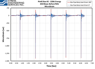
Figure 3: Pipe body raw strain gage data showing peak impact strains and damped oscillations
The connection was made up and broken out multiple times before, during, and after hammering blows to assess the connection’s make-up performance as a result of the impacting blows. A photograph of the make-up and break-out testing is shown in Figure 4. From the CMM arm measurements, the connector showed no plastic deformation after hammering beyond its standard manufacturing tolerances. The connector was able to be made up and broken out with typical responses, showed no surface crack initiations visible via MPI, and passed an API 5C5 water sealability test with bending up to 100% VME stress.
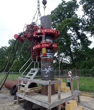
Figure 4: Connection make-up and break-out testing conducted before and after hammer testings
Stress Engineering Services addressed numerous challenges in the test design, implementation, and data reduction during this assessment program. The team was able to use its extensive knowledge of testing systems and equipment to design and implement a multifaceted full-scale test program that extensively evaluated the connector’s performance and delivered valuable results to the client as well as to industry.
** This article appears in the 2017 issue of Stress Talk **

Matt Sanders, PE – Senior Associate, Houston Office
Matt Sanders is a Senior Associate and one of Stress Engineering Services outstanding testing engineers. He specializes in the design and implementation of test programs including fixture design, project management and data analysis. Matt is also involved in downhole tool and screen mechanical testing, OCTG connection testing, ISO 13679 and API 5C5 testing, as well as other load and pressure testing programs.


Leave a Comment Cancel reply
You must Register or Login to post a comment.