Drilling Risers – Life Cycle Condition Based Monitoring and Maintenance Assessment
Stress Engineering Services, Inc. (SES) and LaserStream, LP have joined forces to implement a standard process for critical riser data that can be used to:
- Assess the condition of drilling riser joints
- Determine when important components will need service/replacement
- Assess the remaining life of the component
The process involves collecting detailed measurements that encompass the drilling riser load envelope. These measurements are combined with metocean and drilling conditions collected (in real time or stored) while the operations are in progress. In addition, the Laser Profilometry BEMIS™ (Bore Erosion Measurement and Inspection System) (Figure 1) is used to measure the inner diameter (ID) of the main bore and auxiliary lines between wells to characterize the condition of the drilling riser joints.
Background
The drilling riser on a mobile offshore drilling unit (MODU) is the critical conduit between the drilling rig and well system. The drilling riser typically consists of 75-ft to 90-ft long riser joints connected together. The drilling riser system connects to the top of the BOP, which is latched to the wellhead and casing system on the seafloor. The riser then becomes the main conduit to drill through. During a well control event, high-pressure lines on the outside of the riser main bore are used to control the pressure. In addition to the choke and kill lines, there are hydraulic lines that deliver control fluid to operate the subsea BOP and a mud boost line to deliver additional mud to the bottom of the riser to lift cuttings.
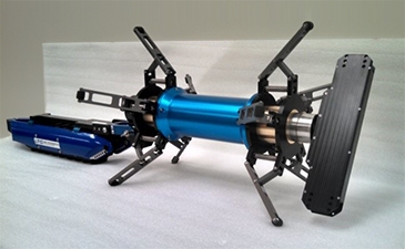
Figure 1: A BEMIS™ system (Image provided by Laser Techniques Company)
Presently, risers are inspected every 5 years. This is usually accomplished by rotating 20% of the riser onshore every year to be disassembled and inspected. This approach requires extensive boat trips and trucking of the riser. Typically, a maximum of 20 riser joints can be transported in one trip on a boat and one riser per truck to an inspection facility, making the logistics of drilling riser inspection very costly.
Data Collection
The approach established by SES and LaserStream utilizes a life cycle condition-based monitoring (CBM), maintenance, and inspection system that can be deployed on a MODU.
The drilling information, metocean conditions, and riser data are collected to determine riser joint fatigue damage. The SES system determines stress and fatigue at any location in a riser system/wellhead/conductor casing via measurements from a number of accelerometers and angular rate sensors placed at strategic locations along the riser, together with analytical riser mode-shape information. Because the only required online inputs are the dynamic riser response, top tension, and mud weight; fatigue can be estimated without knowledge of the impinging currents or other forcing events.
Vibration sensors and data-acquisition electronics are housed in a Subsea Vibration Data Logger (SVDL). The data are then processed using SES-patented technology that integrates a computer algorithm to synthesize stress estimates along the entire riser length using a database of riser dynamic modes (Figure 2). The estimates are then processed chronologically via rainflow counting to determine fatigue damage accumulated during a drilling riser campaign, thereby providing actionable information to the drilling crew.
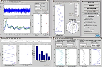
Figure 2: Dashboards displaying accumulated data
The SVDL can be installed individually by a ROV on wellheads and BOPs in an “offline” mode. In the offline mode, the recorded vibration data are retrieved after the measurement campaign (typically several days to a few weeks), and then processed offline to estimate stress and fatigue. A semi-analytical method is used to estimate wellhead fatigue damage directly using the measured BOP stack motion data. Analytical transfer functions are used to directly compute stress time histories and S-N fatigue damage at any location of interest in the drilling riser/conductor/wellhead/BOP system. The offline fatigue monitoring system provides the operator with a useful tool to assess system integrity at any time during a drilling campaign. The semi-analytical method to compute fatigue from measured vibration provides rapid turnaround of raw data to fatigue consumption, enabling informed decisions to be made in adverse conditions.
After the drilling riser joints have been recovered to the surface, the LaserStream BEMIS™ is used to inspect them. The laser ID inspection consists of deploying the BEMIS™ (specifically modified for drilling riser applications) through the ID of the riser via a tethered crawler. The scan starts in the launch tube and travels down the entire riser tube taking measurements. The scanner head rotates at 250 rpm, collecting over 3,000 measurements per rotation. These measurements are accurate to ± 0.002 inch.
The auxiliary lines are inspected in the same manner. Approximately eight riser joints can be inspected per day. The field results are immediately available at the site, and the final report follows in about a week.
This inspection system generates millions of high-resolution data points that can be used to:
1. Determine material loss due to pitting and/or mechanical wear.
2. Characterize features to deduce if they were caused by wireline, drill pipe, corrosion, or a manufacturing flaw.
3. Perform a detailed analysis of the entire tube, including the pin end and ID weld dimensions (including areas where UT techniques cannot provide an adequate inspection).
Handheld UT can then be utilized on areas of concern to validate remaining body wall thickness in that particular area.
Data Analysis
The images are analyzed using the LaserViewer™ software (Figure 3). Accurate mapping of the pipe ID allows locating areas of material loss, which can be measured exactly. This can be performed interactively by moving the cursor over the “pipe map” image.
The anomalies that meet the criteria are identified and measured, along with the location of the feature on the tube. These results are given on a riser tally of inspected specimens, with detailed feature reports for each anomaly identified. The data can also be imported into LaserViewer™ 3D or even SOLIDWORKS® for finite element analysis.
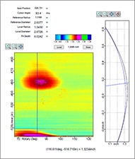
Figure 3: Sample output from BEMIS™ showing a feature depth of 0.0242” @ 526” and 83°
The Assessment Report
With the in-situ monitoring of metocean conditions, drilling conditions, and LaserStream’s ID inspection, the data compiled are extensive and precise and represent a powerful tool to understand the service and present condition of the riser. The original manufacturing condition can be compiled as well (i.e., mill certs, manufacturing reports, weld inspections) as part of the baseline information.
The assessment report provides several important benefits:
1. Assessment of the current condition of the riser, which can be used to determine whether the riser is fit to return to service.
2. A quantitative understanding of any damage and what conditions may have led to the damage (keyseating, wear, corrosion, etc.).
3. Assessment of the fatigue damage to the riser joints and the associated mechanism (wave or VIV).
4. Information for determining when the riser should be rotated out of service or inspected more frequently (CBM).
The report provides a riser tally with all inspection measurements taken. It also indicates where the riser was positioned in the water column and the loads to which it was subjected. This report can be immediately used by the operations team to determine whether the riser is fit to return to service and where it should be placed to balance out its load life. The report also includes the damage signature and the cause of the damage. This damage signature along with the load conditions will allow the operator to begin to understand the origin and may lead to operational adjustments.
When compared to future reports and load history, riser assessment reports will allow the drilling contractor and operator to quantify the damage rate and to link operational trends to such damage. This will allow the drilling industry to utilize a CBM approach. Future inspection frequency can be adjusted as damage and wear rates become better understood. This will allow resources to be deployed only when necessary, instead of on a calendar basis.
The assessment report and SES’s riser modeling expertise, combined with the projected loads, can effectively determine remaining life. Actual load conditions and damage can also be compared to design load assumptions, potentially extending the life of assets that were designed for harsh environments. The user can determine whether the system can be redeployed or replaced. This can also allow actual loads and wear rates to be cycled back into future design work, resulting in improved riser design and manufacturing (Figure 4).
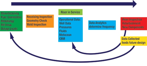
Figure 4: Drilling Riser Life CBM Assessment Process
** This article appears in the 2017 issue of Stress Talk **


Kenneth Bhalla, PhD, CEng – Principal, Houston Office
Kelly Fisher – Business Development Manager, Houston Office
Jason Waligura – Founding Partner, LaserStream LP
Dr. Bhalla is a Principal at Stress and leads the drilling systems group. He has extensive experience in the design, analyses, and operability assessment of Marine Riser systems including Drilling risers, Completion Workover risers, casing systems, and wellhead equipment.
Kelly Fisher is the Business Development Manager at Stress in Houston, where he has worked for the last 12 years assisting professionals in the oil & energy industry with their technical challenges. His skills are primarily in International Sales, Sales, Procurement, Business Development, and Field Service.
Jason Waligura is a founding partner of LaserStream LP. His expertise is in drilling encompassing completion, production and reservoir. His technical experience includes deepwater drilling and completions, startup of new build MODU’s, international operations, and wellsite supervision of critical operations.


Leave a Comment Cancel reply
You must Register or Login to post a comment.