Repurposing Pipelines to Light Liquid Hydrocarbon Service
The recent boom in oil production using hydraulic fracturing (fracking) technology has produced an increased supply of natural gas and other products referred to as ultralight hydrocarbons (ethane, propane, butane). These hydrocarbons present a unique set of challenges in transportation; their inherent tendency to rapidly cool and experience auto-refrigeration during rapid pressure loss presents design challenges for safe operation.
Because new pipeline construction can be challenging due to political and economic constraints, repurposing an existing pipeline, when possible, is a very attractive alternative.
An effective repurposing program requires attention to a number of special considerations when dealing with light hydrocarbons. Stress Engineering Services has developed a multistep approach to assist clients in addressing this problem:
- Determine the applicable code that will govern the pipeline design
- Establish initial “design” parameters
- Perform analyses to evaluate the integrity of the pipeline under the proposed operating conditions with special consideration of failure modes.
- Perform assessments to establish crack inspection criteria for pipeline inspections
To illustrate our approach, we will consider a case-study example: a 12.75” OD x 0.330” WT pipeline with 900# B16.5 flanges constructed of API 5L X60 PS-1 material that will be repurposed to transport ethane as a supercritical fluid at a pressure of 1,200 psig. Each step in the analysis of this example pipeline is described in the sections that follow.
Governing Pipeline Code
The obvious choice for the governing pipeline code is the original code of construction; however, for a variety of reasons, including the simple fact that adequate documentation demonstrating code conformance is often unavailable, this is not always the best choice.
The ASME pipeline codes often considered when repurposing pipelines include the following:
- 3 Process Piping
- 4 Pipeline Transportation Systems for Liquids and Slurries
- 8 Gas Transmission and Distribution Piping Systems
B31.4 will be used as the Code for the example scenario following typical selection for this service.
Initial Design Parameters
The primary design parameters that need to be established for the existing pipeline are (1) minimum wall thickness (including the establishment of a corrosion allowance) and (2) design pressure. These values are calculated based on allowable stresses in the applicable code. Our approach to determining the design pressure is to determine the maximum allowable pressure after accounting for the necessary mill tolerance, corrosion allowance and flange ratings.
Considering our example pipeline, the maximum allowable pressure per the requirements of B31.4 is 2,236 psi. This coincidentally corresponds relatively closely to the 2,220 psi rating of the 900# flanges on the pipeline.
Thus, the design pressure is established and set as 2,220 psi. At this pressure, the minimum wall thickness is 0.328”, so the pipeline should be adequate for its intended service.
Fracture Prevention Analysis
After initial design parameters are established, a series of analyses are performed to ensure the integrity of the pipeline under the proposed operating conditions. Three types of analyses are considered in our approach:
- Ductile Fast Fracture (B31.4 Paragraph 403.7.4)
- Auto-refrigeration/Brittle Fracture (B31.4 Paragraph 403.7.3)
- Engineering Criticality Assessments
Ductile Fast Fracture
Ductile fast fracture is a phenomenon whereby an initial through-wall fracture in a pipeline and the subsequent rapid exit of the transported fluid, results in a ductile fracture propagating along the length of the pipeline. The risk for ductile fast facture exists when the contents of the pipeline are gases or volatile liquids under high pressure. In the event of a through-wall crack, as the compressed fluid escapes from the pipeline, the drop in pressure of the contained fluid propagates as a decompression (expansion) wave traveling away from the crack opening at the speed of sound in the fluid. At the same time, the fluid rushes out of the propagating crack opening in the opposite direction.
The resultant velocity of the decompression wave front, relative to the pipeline, is the difference between these two velocities.
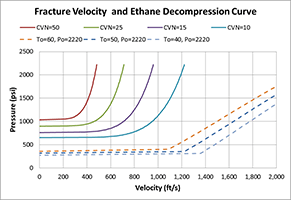
Figure 1
The Battelle two-curve method is commonly used to evaluate susceptibility to ductile fast fracture by comparing the velocity of crack propagation to the velocity of the decompression wave. Figure 1 shows the results of the ductile fast fracture analysis for the example pipeline. The figure includes two sets of curves. The solid curves show fracture velocity for different levels of material toughness as indicated by Charpy V-notch (CVN) energies. The dashed curves show gas decompression velocity for ethane fluid (supercritical to gas vapor). Should a decompression curve intersect a fracture velocity curve, this would indicate that there is a range of pressure at which there is a risk of driving a ductile fracture. When the two sets of curves do not intersect (as in this example), the decompression wave travels faster and a crack is likely to self-arrest.
Brittle Fracture Analysis
Auto-refrigeration (AR) is the unintentional and uncontrolled phase change of a hydrocarbon or other volatile substance from a liquid to a vapor that results in refrigeration or rapid cooling of the liquid and its containment. Brittle fracture (BF) is the sudden and often catastrophic fracture of a material accompanied by little or no plastic deformation. AR often leads to BF of ferrous metals that exhibit a ductile-to-brittle transition at low temperatures. Pipeline analysis to prevent BF usually aims at establishing a minimum allowable temperature (MAT) for the pipeline. AR/BF is of primary concern during transient operations such as inventory and de-inventory of the pipeline, and during upset conditions such as a leak in the pipe wall.
AR/BF can be evaluated using the methodology of API-579/ASME FFS-1 Part 3. The standard exemption curve methodology utilized in API 579 matches the methodology in Chapter 323.2.2 of ASME B31.3 and UCS-66 of ASME Section VIII Div 1. The allowable stresses for pipeline codes such as B31.4 and B31.8 sometimes exceed the stress levels considered in developing these methods. We address this by considering the methods of ASME BPVC Section VIII, Div 2 and its development basis as documented in WRC 528, which incorporates fracture mechanics principles to address the higher stress levels.
AR/BF analysis methodologies incorporate an exemption curve to determine the MAT of the pipeline and a temperature reduction curve to give credit for operation below design pressure. The result is an MAT curve that covers all pressures up to the design pressure.
For buried (constrained) pipeline systems, an additional factor that needs to be considered in determining the MAT is the increase in longitudinal stress as the temperature decreases. This condition is addressed as a separate MAT curve for longitudinal stress that is determined iteratively taking into account the stress increase with decreasing temperature due to constrained contraction.
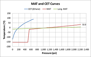
Figure 2
Figure 2 shows an MAT curve and a longitudinal MAT curve for the example 12” pipeline. The higher temperature indicated by the two methods (curves) controls the MAT for a given pressure. A third curve shown in the figure is the critical exposure temperature (CET), which is the flash curve for ethane.
Engineering Criticality Assessment
As part of the repurposing analysis, an engineering criticality assessment (ECA) is also performed using fracture mechanics principles to gain an understanding of the flaw tolerance of the subject pipeline system. By determining critical crack size under static loading, it is possible to establish acceptance criteria for pipeline inspections.
Fracture mechanics assessments are performed in accordance with API 579-1/ASME FFS-1, Part 9. The Level 2 failure assessment diagram (FAD), which is the general assessment procedure, is employed to evaluate a flaw against failure criteria.
The FAD procedure considers crack propagation by fracture and by plastic collapse of the remaining ligament. An assessment line is drawn on the particular FAD diagram, and calculations for a crack provide the coordinates of an assessment point. The crack is considered acceptable if this assessment point lies within the area of the FAD.
A critical crack size curve is the result of a parametric FAD analysis. This curve defines a boundary of acceptability for various crack size combinations.
For the example pipeline case, Figure 4 and Figure 5 show critical crack size curves for axial cracks (driven by hoop stress) and circumferential cracks (driven by axial stress), respectively. As indicated, crack sizes below the curves are acceptable while crack sizes above the curves are not.
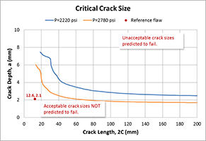
Figure 3
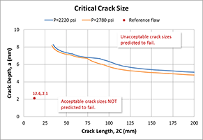
Figure 4
Conclusions
The increasing need to transport light liquid hydrocarbons has led to increased activity to repurpose existing liquid pipelines for this service. In evaluating repurposed pipelines, it is essential to consider specific failure mechanisms introduced by the proposed volatile contents. Pipeline construction Codes (B31.4 and B31.8) provide guidance on the design and fracture checks required to ensure the integrity of the pipeline after its repurposing to light liquid hydrocarbon service. This article outlined analysis checks and methodologies, based on our own analytical approach, to ensure a safe and reliable design.
** This article appears in the 2017 issue of Stress Talk **


Daniel Ayewah, PE – Associate II, Houston Office
Ralph King, PE – Sr. Staff Consultant, Houston Office
Daniel has a background in fracture and solid mechanics analyses involving a wide range of materials, evaluating critical crack sizes and predicting crack growth rates using both classical solution methods and using finite element models.
Ralph is a 35-year experienced mechanical engineer with a broad range of technical experiences including maintenance / reliability engineering of fixed, fired and rotating equipment, process / production engineering and process safety.


Leave a Comment Cancel reply
You must Register or Login to post a comment.