Six Degrees of Freedom Rocket Engine Duct Test
Many of today’s cutting-edge rocket engines use liquid natural gas (fuel) and liquid oxygen (oxidizer) to create thrust, which pushes the rocket forward and steers it when the angle of the engine is changed by gimballing. Transporting fuel and oxidizer into a gimballing engine requires big, flexible connecting hoses or ducts that must withstand cryogenic temperatures, pressures, forces and torques.
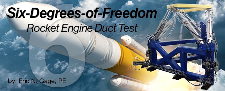
Stress Engineering Services received a request from a private space company to perform two tests on these types of rocket engine ducts with the goals of 1) understanding how robust each duct was under peak loading conditions, and 2) generating stiffness test data for future analysis. To achieve these goals, we constructed a custom Stewart Table (or Hexapod) test frame to perform 6-degrees-of-freedom (6DOF) on two ducts.

During the test, each duct outlet was anchored in the frame base. The inlet of each duct was then secured to the moving top section of the test frame, driven by six independent hydraulic cylinders. This allowed any desired combination of forces in the X, Y and Z directions and torques in those same X, Y and Z directions. The test was a complete success for both the client and Stress Engineering Services.
Test data was obtained from four main sources:
- Tri-axial strain gauges were applied to the duct exterior surfaces and supporting brackets at locations selected by the client.
- Pressure transducers monitored the internal pressures inside the various duct interior regions.
- One 6DOF load cell located at the point of loads application and six uniaxial force transducers located in line with the hydraulic cylinders provided measurement of forces and torques.
- A Digital Image Correlation (DIC) system was used to track the exact translation and rotation of the duct inlet while forces and torques were applied. This system uses precise parallax calculations between two calibrated digital cameras to calculate these geometric offsets. A second DIC system was used to monitor selected regions in the test setup and report large area strain fields.

Initial testing of the duct went well, but as higher loads were reached, the client felt that the test frame was not stiff enough to continue. Within a week, our staff modified the frame with additional bracing turnbuckles and increased its rigidity, successfully earning client approval.
Before the second duct test began, we increased the frame stiffness even further by adding 5-inch-thick steel plates. Although it is impractical to make overly heavy rocket parts, rocket part test frames may be produced as large and as strong as desired.
Many of our engineers are well versed in complicated and multiple component hydraulic controls, but we have never seen a test stand with such a complicated interplay of cylinder interaction.
To complete the tests successfully, we applied a precise array of multiple forces and torques to the inlet end of each duct in order to determine how much it moved. The science of accomplishing this depended on the relative stiffness of the duct test sample to the test frame. This presents a challenge because the relative stiffness continuously changes as the test article deflects, causing re-distribution of loads among connecting brackets and hardware on the duct. To address this, an iterative “baby steps” process should be employed to creep up to the correct force and torque values while staying within the allowed tolerances.
“To our knowledge, a pure load control system like this does not exist anywhere else.”
– Dr. Steven Kinyon, PE, Stress Engineering Services
One must have the necessary experience and equipment, testing strengths and adaptability to apply six degrees of displacement and rotation (surge, heave, sway, pitch, yaw, roll) on a test article to successfully measure loads and moments. This project demonstrates that the Stewart table is a useful tool for applying loads (Fx, Fy, Fz, Mx, My, Mz) and measuring corresponding movements.

Eric N. Gage, PE – Principal, Houston Office
Eric is an experienced mechanical engineer skilled in managing large- and small-scale testing and development projects. He is a registered professional engineer in the State of Texas and is adept at designing and analyzing mechanics and hydraulic systems. A Stress Engineering Services team member for nearly a quarter of a century, he is one of our most respected test engineers. Eric has a BS in Mechanical Engineering from the University of Oklahoma.


Leave a Comment Cancel reply
You must Register or Login to post a comment.